Aeration in Wastewater Treatment
- Introduction [1]
Aeration is a unit operation of fundamental importance in a large number of aerobic wastewater treatment processes. When a liquid is deficient in a gas (oxygen, in this case), there is a natural tendency of the gas to pass from the gas phase, where it is present in sufficient concentrations, to the liquid phase, where it is deficient.
The major purpose of dissolving air is to provide oxygen to be used by microorganism in the process of wastewater treatment.
Oxygen is a gas that dissolves poorly in the liquid medium. For this reason, in various wastewater treatment systems it is necessary to accelerate the natural process, in such a way that the oxygen supply may occur at a higher rate, compatible with the biomass utilisation rate. Among the wastewater treatment processes that use artificial aeration are aerated lagoons, activated sludge and its variants, aerated biofilters and other more specific processes. In terms of sludge treatment, aerobic digesters also use artificial aeration.
There are two main forms of producing artificial aeration:
- introduce air or oxygen into the liquid (diffused air aeration)
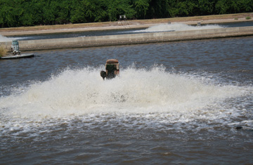
- cause a large turbulence, exposing the liquid, in the form of droplets, into the air, and also permitting the entrance of atmospheric air into the liquid medium (surface or mechanical aeration).
Figure 1 presents schematically the principles of aeration by diffused air and mechanical aeration.
There is another way of transferring oxygen to the liquid medium is described: gravity aeration (steps, weirs, cascades).
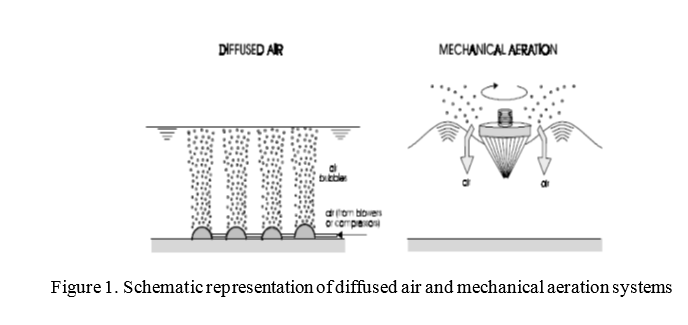

Figure 2. Shows some of Aeration units like turbine aerator with an air sparger; porous ceramic diffuser; and surface aerator.
- Gas transfer mechanisms
There are two basic mechanisms for the transfer of oxygen from the gas phase to the liquid phase:
- Molecular diffusion
- Turbulent diffusion
2.1 Molecular diffusion
Molecular diffusion can be understood as the tendency of any substance to spread itself uniformly in the space available.
For a water body of unlimited depth, exposed to the gas phase through a surface A, the mass transfer rate dM/dt due to the diffusion of the gas molecules in the liquid phase is defined by Fick’s law (P¨opel, 1979): [2]
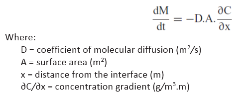
It is important to note that, for a certain gas, only the concentration gradient determines the diffusion rate per unit area. The negative sign indicates that the direction of diffusion is opposite to the positive concentration gradient.
For oxygen, the values of the diffusion coefficient are presented in Table 1.

Two theories frequently used to explain the gas transfer mechanism are: [2]
- Two-film theory. In the gas–liquid interface there are two films, a gas film and a liquid film. The gas is absorbed and transported by molecular diffusion and mixing (convection) by the gas film and subsequently by the liquid film. The films are considered as stagnant and with a fixed thickness.
The two-film theory is simpler but provides a good answer in most cases (Metcalf & Eddy, 1991). [3]
- Penetration theory. The penetration theory does not assume stagnant films, but fluid elements that are momentarily exposed to the gas phase in the liquid interface. During this exposure time the gas diffuses in the fluid elements penetrating the liquid. Differently from the two-film theory, the penetration process is described by an unsteady diffusion. The exposure time is considered very short (< 1 s) for steady diffusion conditions to prevail. The penetration theory is more soundly theoretically based.
2.2 Turbulent diffusion
In sewage treatment with artificial aeration, the main gas transfer mechanism occurs through the creation and renewal of the interfaces
The turbulent flux generated by artificial aeration consists of a complex secondary movement that surpasses the primary movement of the liquid mass. The turbulence is characterized by oscillations and eddies that transport fluid particles from one layer to another, with variable velocities. The turbulent movement, which is erratic in direction, magnitude and time, can be defined only probabilistically (O’Connor and Dobbins, 1958). [4]
As mentioned, gas transfer by turbulent diffusion is much higher than by molecular diffusion. The basic structure of the gas transfer formulation can be maintained, with adaptations only in the sense of simplifying its presentation.
- FACTORS OF INFLUENCE IN OXYGEN TRANSFER
The oxygen transfer rate of the aeration equipment to be installed in a wastewater treatment plant is frequently determined in different conditions under which it will operate (operating conditions). Therefore, it is important to be able to quantify the factors that influence the oxygen transfer rate, to allow the estimation of the transfer rate under operating conditions, based on results obtained in tests undertaken under standardized conditions.
The factors of major influence on the oxygen transfer rate are:
- temperature
- atmospheric pressure (altitude)
- dissolved oxygen concentration
- characteristics of the wastewater
- characteristics of the aerator and the geometry of the reactor
- MECHANICAL AERATION SYSTEMS
The main mechanisms of oxygen transfer by mechanical surface aerators are (Malina, 1992): [5]
- Atmospheric oxygen transfer to the droplets and the fine films of liquid sprayed in the air
- Oxygen transfer at the air-liquid interface, where the falling drops enter into contact with the liquid in the reactor
- Oxygen transfer by air bubbles transported from the surface to the bulk of the liquid medium
The more commonly used mechanical aerators can be grouped according to:
– Classification as a function of the rotation shaft:
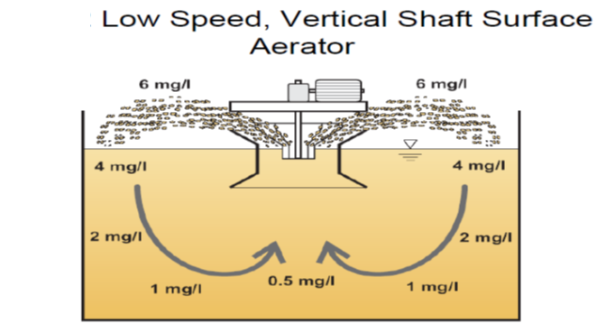
- vertical shaft aerators
- low speed, radial flow
- high speed, axial flow
- horizontal shaft aerators
- low speed
-Classification as a function of the supporting:
- fixed aerators
- floating aerators
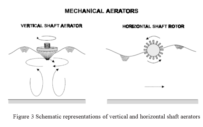
Figure 3. Shows schematically mechanical aerators with vertical and horizontal shafts.
The power of mechanical aerators usually varies between 5 HP and 100 HP, although, in special conditions, lower and higher values can be found.
In mechanical aerators, the submergence of the impellers in relation to the water level is a very important aspect in terms of oxygen transfer and energy consumption. The following situations can occur:
- Adequate submergence. The performance is optimal. There is good turbulence and absorption of air with relation to the oxygen consumption.
- Submergence above the optimal. The unit tends to function more as a mixer than as an aerator. The energy consumption increases without being accompanied by a substantial increase in the oxygen transfer rate.
- Submergence below the optimal. Only a surface spray is formed in the vicinity of the aerator, without creating an effective turbulence. The energy consumption and the oxygen transfer rate decrease.
The installation of the aerator must follow the manufacturer’s instructions. Besides this, local tests should be carried out in order to obtain the optimal submergence in the reactor in question.
In many activated sludge plants, the oxygen transfer rate can be varied in such a way as to adjust itself to the variations in the oxygen utilization rate. The variation can be manual or automated, by means of timers or sensors for dissolved oxygen in the reactor. Listed below are some of the most common forms of varying the oxygen transfer rate in mechanical aerator systems:
- switch on and off certain aerators
- vary the rotation speed of the aerators
- vary the submergence of fixed aerators through the alteration of the level of the outlet weir (change in the water level)
- vary the submergence through the change of the level of the aerator shaft
- DIFFUSED AIR AERATION SYSTEMS
The diffused air aeration system is composed of diffusers submerged in the liquid, air distribution piping, air transport piping, blowers, and other units through which the air passes. The air is introduced close to the bottom of the tank and the oxygen is transferred to the liquid medium while the bubble rises to the surface.
The main diffused air systems can be classified according to the porosity of the diffuser and the size of the bubble produced:
- porous diffuser (fine and medium bubbles): plate, disc, dome, tube (ceramic, plastic, flexible membrane)
- non-porous diffuser (coarse bubbles): nozzles or orifices
- other systems: jet aerator, aspirating aerator, U-tube aerator
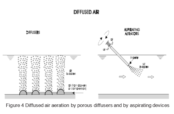
Figure 4 presents schematics of the aeration by porous diffusers and aspirating devices. Aspirating devices have an impeller at the lower end (immersed in the liquid), which, when rotating, create a negative pressure, sucking in atmospheric air through a slot situated at the upper end (outside the liquid). Air is diffused into the liquid medium in the form of small bubbles, which are responsible for the oxygenation and mixing of the liquid mass. The aspirating aerators are presented in some texts as mechanical aerators, since they have motors that rotate outside the liquid, and in other texts as diffused air aerators, because they generate air bubbles in the liquid medium
The diameters of the bubbles considered in the classification of the aeration type are (ABNT, 1989): [6]
- fine bubble: diameter less than 3 mm
- medium bubble: diameter between 3 and 6 mm
- coarse bubble: diameter greater than 6 mm
In general, the smaller the size of the air bubbles, the greater the surface area available for gas transfer, that is, the greater the oxygenation efficiency. For this reason, aeration systems with fine bubbles are the most efficient in the transfer of
oxygen.
The oxygen transfer efficiency of the porous diffusers decreases with the use ,due to the internal or external clogging. The internal clogging is due to impurities in the air that are not removed by the filter. The external clogging is due to bacterial growth on the surface, or the precipitation of inorganic compounds.
The oxygen transfer rate can be changed to adjust itself to the oxygen consumption through the control of the blowers and the air distribution system, thus allowing energy savings.
By
Ahmed Ahmed Elserwy
Water & Environmental Consultant
Ain Shames University, Faculty of Science
References
[1] Marcos von Sperling ,2007. Basic Principles of Wastewater Treatment ,IWA Publishing, London, UK,page 161.
[2] PO¨ PEL, H.J. (1979). Aeration and gas transfer. 2. ed. Delft, Delft University of Technology. 169 p.
[3] METCALF & EDDY (1991). Wastewater engineering: treatment, disposal and reuse.
Metcalf & Eddy, Inc. 3. ed, 1334 pp.
[4] O’CONNOR, D.J., DOBBINS, W.E. (1958). Mechanism of reaeration in natural streams. Journal Sanitary Engineering Division, ASCE, 123. p. 641–666.
[5] MALINA, J.F. Biological waste treatment. In: Semin´ario de transferˆencia de tecnologia.Tratamento de esgotos. ABES/WEF. Rio de Janeiro, 17–20 Aug 1992. p. 153–315.
[6] ABNT (1989). Projeto de esta¸c˜oes de tratamento de esgotos. NBR-570 (in Portuguese). ARCEIVALA, S.J. (1981). Wastewater treatment and disposal. Marcel Dekker, New York.892 p.

