Dewatering
Dewatering is the physical operation of reducing the moisture content of sludge and biosolids to achieve a volume reduction greater than that achieved by thickening. Dewatering, because of the substantial volume reduction, decreases the capital and operating costs of subsequent handling of solids.
Dewatering sludge and biosolids from a solids concentration of 4 to 20% reduces the volume to one-fifth and results in a nonfluid material.
The dewatering processes that are commonly used include mechanical processes such as centrifuges, belt filter presses, and pressure filter presses; and natural processes such as drying beds and drying lagoons. The main variables in any dewatering process are solids concentration and flow rate of the feed stream, chemical demand and solids concentration of dewatered sludge cake, and side stream. The selection of particular process is determined
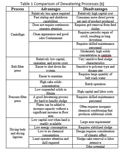
by the type and volume of sludge to be dewatered, characteristics such as dryness required of the dewatered product, and space available. Table 1 presents a comparison of the most commonly used dewatering processes. [1]
The solid-liquid separation could be classified into the following four categories: (1) pretreatment; (2) thickening; (3) filtration, and (4) post-treatment. Sludge dewatering reduces the sludge volume to facilitate the subsequent treatment/disposal processes. Inefficient sludge dewatering could significantly increase transportation, handling and final disposal costs. [2]
Centrifugal Dewatering
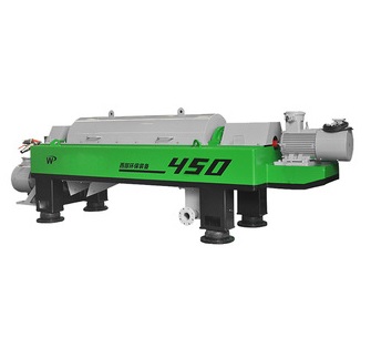
Dewatering of municipal sludge by centrifugation has been widely used in both the United States and Europe. Similar to its application in thickening, it is the process in which a centrifugal force of 500 to 3000 times the force of gravity is applied to sludge to accelerate the separation of the solids and the liquid.
Two basic categories of centrifuges are used for municipal wastewater sludge dewatering: imperforate basket and solid bowl. A third type, the disk nozzle centrifuge, has been used for thickening sludge but has seldom been used for dewatering. Because of the improved design and efficiency of the solid bowl centrifuges in the past few years, imperforate basket centrifuges have fallen out of favor in the municipal market and are being replaced by solid bowl machines.
The main components of a solid bowl centrifuge (also known as continuous decanter scroll or helical screw conveyor centrifuge) are the base, cover, rotating bowl, rotating conveyor scroll, feed pipe, gear unit, backdrive, and main drive . The base provides a solid foundation to support the centrifuge. Vibration isolators below the base reduce the transmission of vibration from the centrifuge to its foundation. The cover that encloses the
rotating bowl assembly completely serves as a safety guard. It also helps contain odors and dampens the noise.
The rotating bowl of the centrifuge consists of a cylindrical-conical design; the proportion of the cylindrical to conical shape varies depending on the manufacturer and the type of centrifuge. The conveyor scroll fits inside the bowl with a small clearance between its outer edge and the inner surface of the bowl. The conveyor rotates, but at a slightly lower or faster speed than the bowl. This difference in speed between the bowl and the conveyor scroll allows the solids to be conveyed from the zone of the stationary feed pipe where the sludge enters the bowl, to the dewatering beach, where the sludge cake is discharged. The dilute stream called centrate is discharged at the opposite end of the cake discharge port. The differential speed is controlled by the gear unit and the backdrive. Depending on the type of sludge, cake solids concentration varies from about 15 to 36%. Centrifuges are available with capacities as low as 40 L/min (10 gpm) to more than 3000 L/min (800 gpm).
Solid bowl centrifuges are available in both countercurrent and concurrent bowl designs (see Figure 1). In the countercurrent design, the sludge feed enters through the small-diameter end of the bowl, and the dewatered sludge cake is conveyed toward the same end. In the concurrent fl ow design, the sludge feed enters through the large-diameter end of the bowl, and the sludge cake is conveyed toward the opposite end.
Because of improvements in the design of the solid bowl centrifuges, cake solids concentrations in excess of 40% have been reported. These machines, known as high-solids (also called high-torque) centrifuges or centripresses, have a slightly longer bowl length, a reduced differential speed, higher torque, and a modified conveyor that presses the solids within the beach end of the centrifuge. These centrifuges may require higher polymer dosages to achieve higher cake solids concentrations.
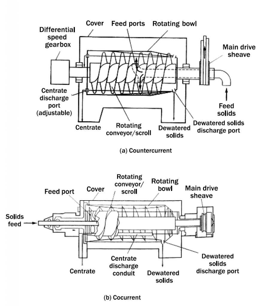
.bowl centrifuge dewatering. [Parts (a) and (b) from Metcalf & Eddy, 2003
By
Ahmed Ahmed Elserwy
Water & Environmental Consultant
Technical Manager Louts for Water Treatment
References
[1] Wastewater sludge processing / Izrail S. Turovskiy, P. K. Mathai, John Wiley & Sons, Inc., Hoboken, New Jersey,2006, p 106.
[2] L. K. Wang, Y. T. Hung, and N. S. Shammas (eds.), Physicochemical Treatment Processes. Humana Press, Totowa, NJ (2005) ,p 684.
[3] Metcalf & Eddy, Tchobanoglous, G., Burton, F. L., Stensel, H. D. “Wastewater engineering: treatment and reuse/Metcalf & Eddy, Inc.”, Tata McGraw-Hill, 2003.
